H1 Overview
Component Overview
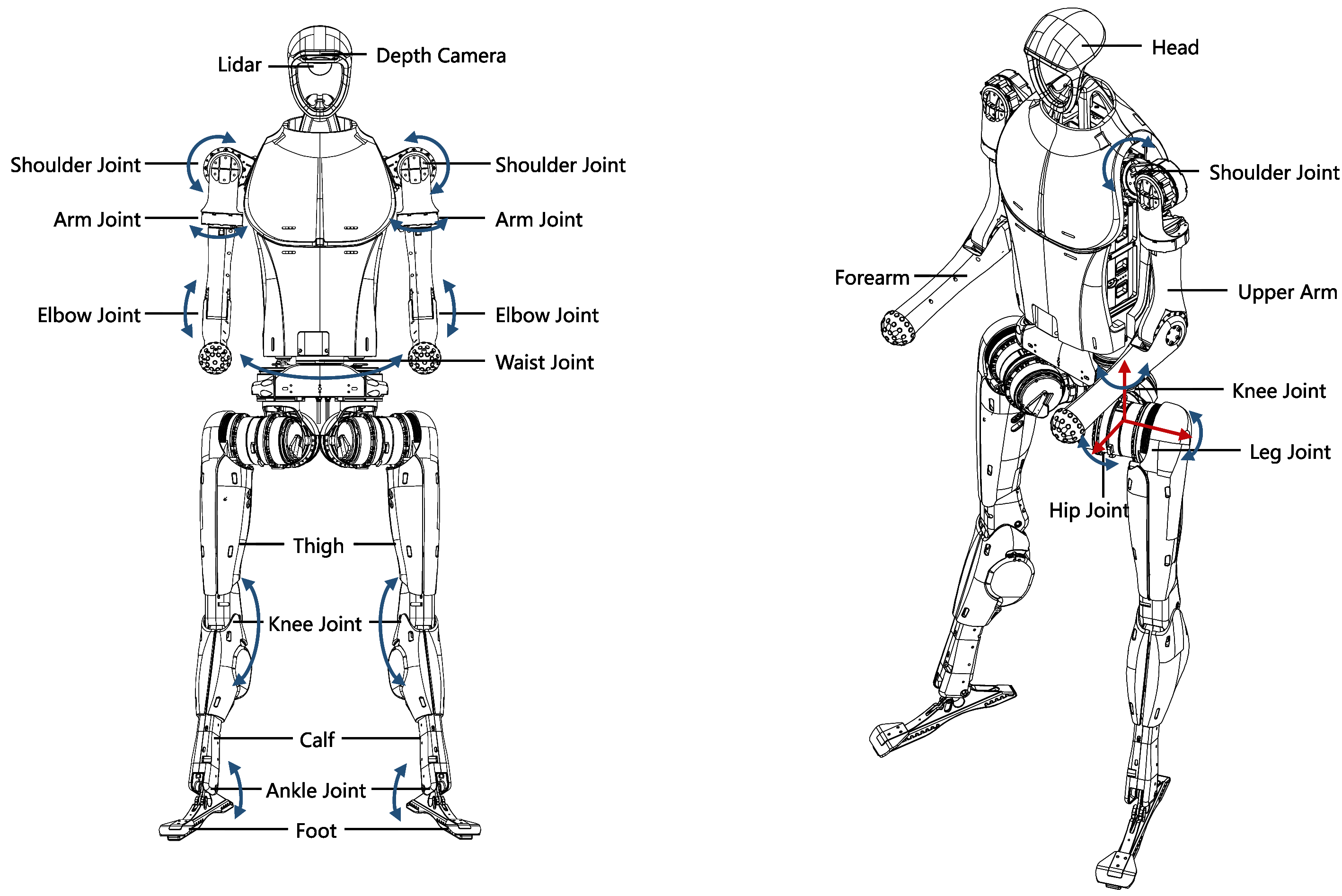
The H1 robot comprises upper and lower bodies, each featuring multiple degrees of freedom. The single arm includes joints for body-shoulder, shoulder, upper arm, and elbow movements, while the single leg features joints for hip, leg, knee, and ankle motions. Additionally, the waist section offers a waist joint. In total, the robot boasts 19 degrees of freedom, enabling precise motion and posture control through 19 joint motors.
Electrical Interfaces
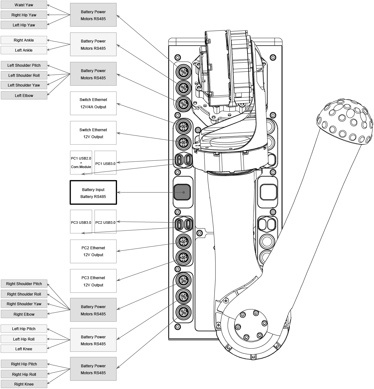
Located on the right side of the H1 robot, the electrical interfaces facilitate connections to various components such as body joint motors, sensor peripherals, and Ethernet ports. This design simplifies debugging, troubleshooting, and secondary development processes.
On-board Computers
The H1 robot comes equipped with a “Motion Control Computing Unit” and optionally a “Development Computing Unit” (additional expansion unit available).
Component |
Motion Control Computing Unit (PC 1) |
Development Computing Unit (PC 2, PC 3) |
|---|---|---|
Model |
i5-1235U |
i7-1255U / i7-1265U |
Number of Cores |
10 |
10 |
Number of Threads |
12 |
12 |
Max Turbo Frequency |
4.40 GHz |
4.70 GHz & 4.80 GHz |
Memory |
8GB |
16GB & 32GB |
Memory Type |
LPDDR5 5200 MT/s (dual-channel) |
LPDDR5 5200 MT/s (dual-channel) |
Cache |
12 MB Intel® Smart Cache |
12 MB Intel® Smart Cache |
Storage |
500GB or more |
500GB or more |
Intel® Graphics Processing Unit |
None |
6.0 |
GPU |
Intel® Iris® Xe Graphics eligible |
Intel® Iris® Xe Graphics eligible |
Max Dynamic Frequency of GPU |
1.20 GHz |
1.20 GHz |
Gauss and Neural Accelerator |
3.0 |
3.0 |
Intel® Deep Learning Boost |
Yes |
Yes |
Intel® Adaptix™ Technology |
Yes |
Yes |
Intel® Hyper-Threading Technology |
Yes |
Yes |
Instruction Set |
64-bit |
64-bit |
OpenGL |
4.6 |
4.6 |
OpenCL |
3.0 |
3.0 |
DirectX |
12.1 |
12.1 |
IP Address |
Unaccessible |
192.168.123.162, 192.168.123.163 |
Attention
The “Motion Control Computing Unit” is exclusively reserved for Unitree motion control programs and is not accessible for external use. Developers are limited to utilizing the “Development Computing Unit” for secondary development. For the initial username and password, please contact our technical support team.
In the table above, the PC3 “Development Computing Unit” is an optional configuration, with its IP address set to 192.168.123.163.
The CPU module may be upgraded to a more advanced version, provided that the performance meets or exceeds the specifications listed.
Lidar
The H1 robot’s head incorporates the MID-360 Lidar (IP: 192.168.123.120), which offers superior environmental perception capabilities. Employing omnidirectional, full-angle scanning technology, it delivers real-time and precise environmental data, facilitating accurate recognition and measurement of surrounding objects.
Depth Camera
Equipped with the D435i depth camera, the H1 robot’s head boasts exceptional visual perception capabilities. This enables more precise perception and understanding of the surrounding environment, allowing for accurate spatial perception and obstacle detection. Consequently, the robot can interact intelligently with its environment and adapt to various scenarios effectively.
M107 Joint Motor
The H1 robot utilizes the self-developed M107 joint motor by Unitree, known for its outstanding performance. Featuring a maximum torque of 360N.m and a maximum tension of 10000N (under equivalent conditions of a 3.5cm force arm), this motor’s hollow axle design makes it lightweight and compact. Additionally, equipped with dual encoders, it provides more accurate position and velocity feedback, meeting the requirements of high-precision control.
Joint Numbering and Joint Limits
The table below provides an overview of the joint numbering system and their respective movement limits. Each joint is identified by a unique number and name, detailing its specific range of motion in radians. These constraints define the permissible angular movement for each joint, ensuring safe and effective operation. The data serves as a reference for configuring, calibrating, or troubleshooting the system’s kinematics.
Joint Number |
Joint Name |
Limits (radians) |
|---|---|---|
8 |
right_hip_yaw_joint |
-0.43~+0.43 |
0 |
right_hip_roll_joint |
-0.43~+0.43 |
1 |
right_hip_pitch_joint |
-3.14~+2.53 |
2 |
right_knee_joint |
-0.26~+2.05 |
11 |
right_ankle_joint |
-0.87~+0.52 |
7 |
left_hip_yaw_joint |
-0.43~+0.43 |
3 |
left_hip_roll_joint |
-0.43~+0.43 |
4 |
left_hip_pitch_joint |
-3.14~+2.53 |
5 |
left_knee_joint |
-0.26~+2.05 |
10 |
left_ankle_joint |
-0.87~+0.52 |
6 |
torso_joint |
-2.35~+2.35 |
12 |
right_shoulder_pitch_joint |
-2.87~+2.87 |
13 |
right_shoulder_roll_joint |
-3.11~+0.34 |
14 |
right_shoulder_yaw_joint |
-4.45~+1.3 |
15 |
right_elbow_joint |
-1.25~+2.61 |
16 |
left_shoulder_pitch_joint |
-2.87~+2.87 |
17 |
left_shoulder_roll_joint |
-0.34~+3.11 |
18 |
left_shoulder_yaw_joint |
-1.3~+4.45 |
19 |
left_elbow_joint |
-1.25~+2.61 |
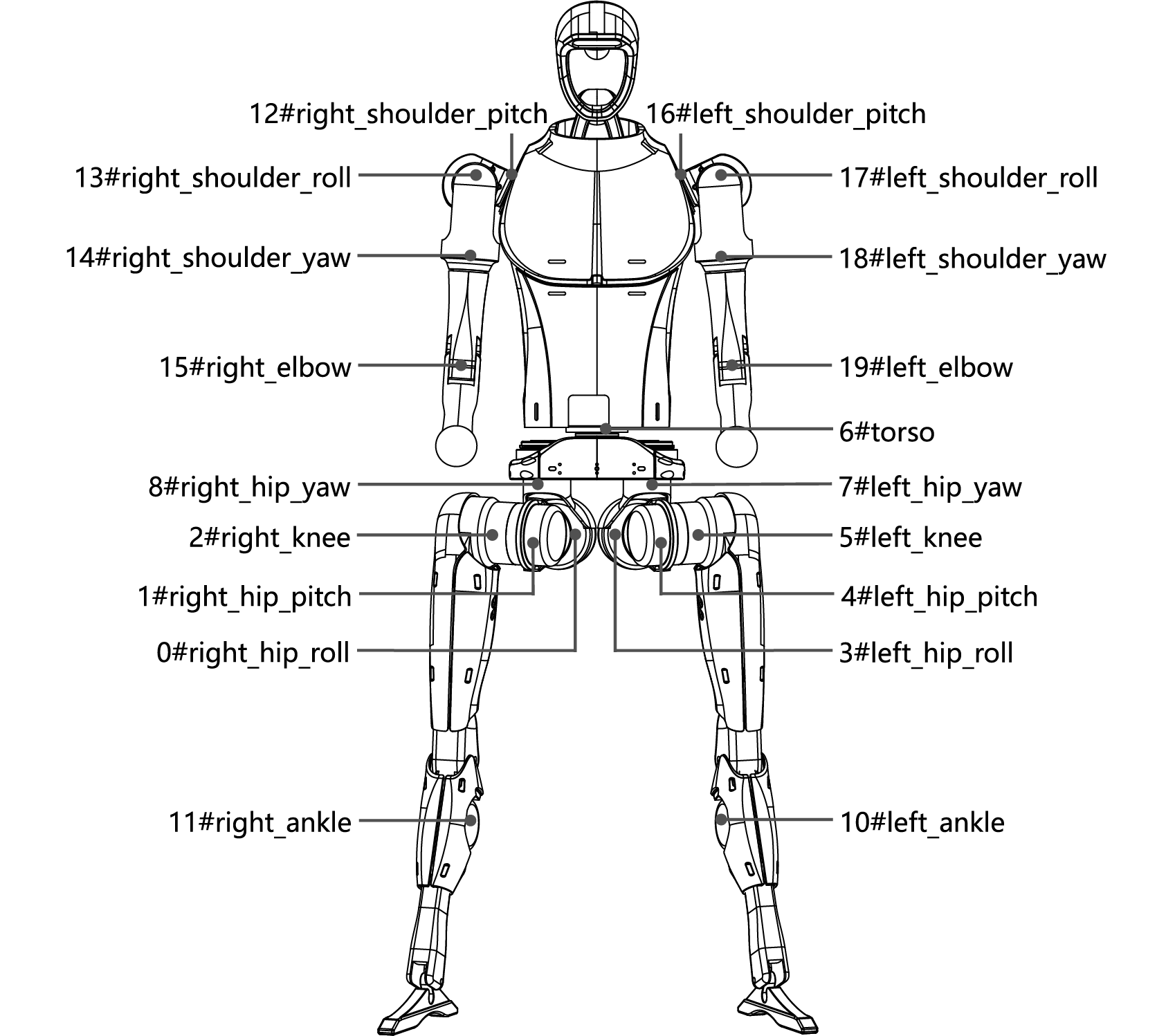
The image below displays the Unitree H1 humanoid robot with all joints labeled. It serves as a visual reference, correlating the joint numbers and names listed in the table to their positions on the robot.
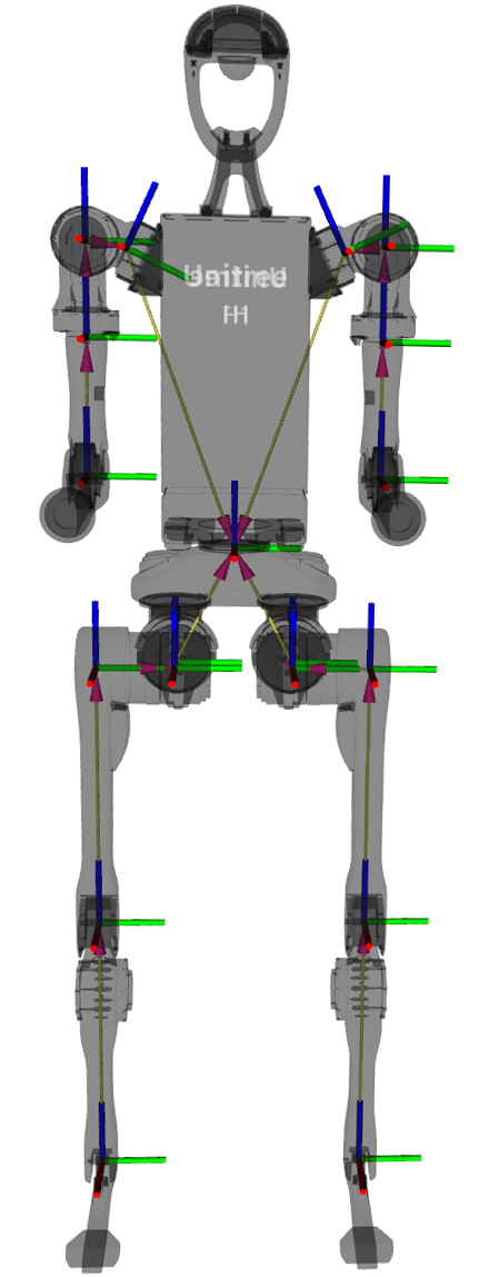
Reference Frame, Joint Axes, and Zero Position
In the zero-degree configuration of all joints, the coordinate system is depicted as shown in the figure below. The x-axis is represented by the red line, the y-axis by the green line, and the z-axis by the blue line.