Changing Motor IDs
Requirements
1 x RS-485 Module: This module is crucial for enabling communication between your computer and the motor.
1 x Cable: A suitable RS-485 communication cable to connect the motor and RS-485 module.
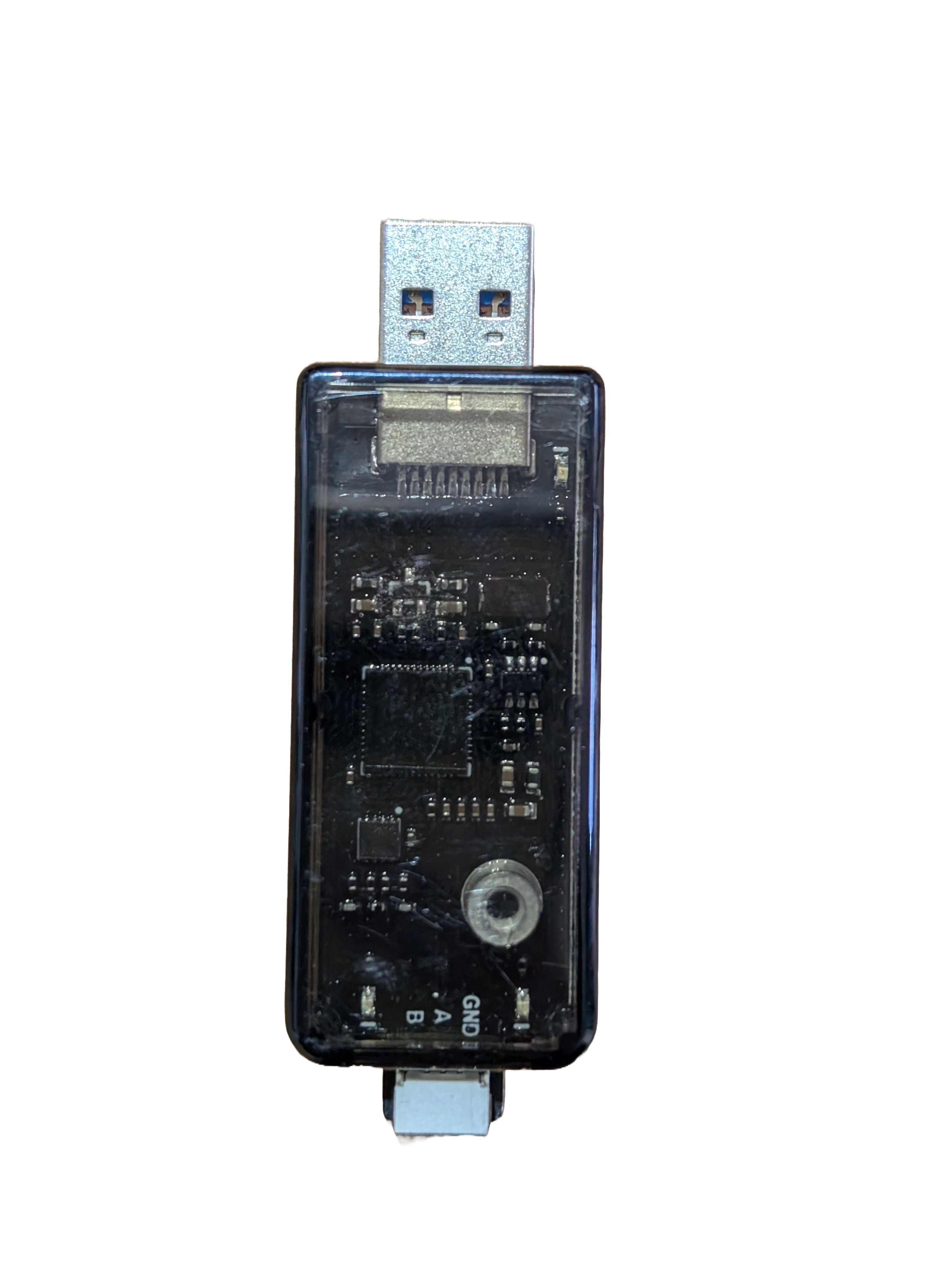
Rs485 Module |
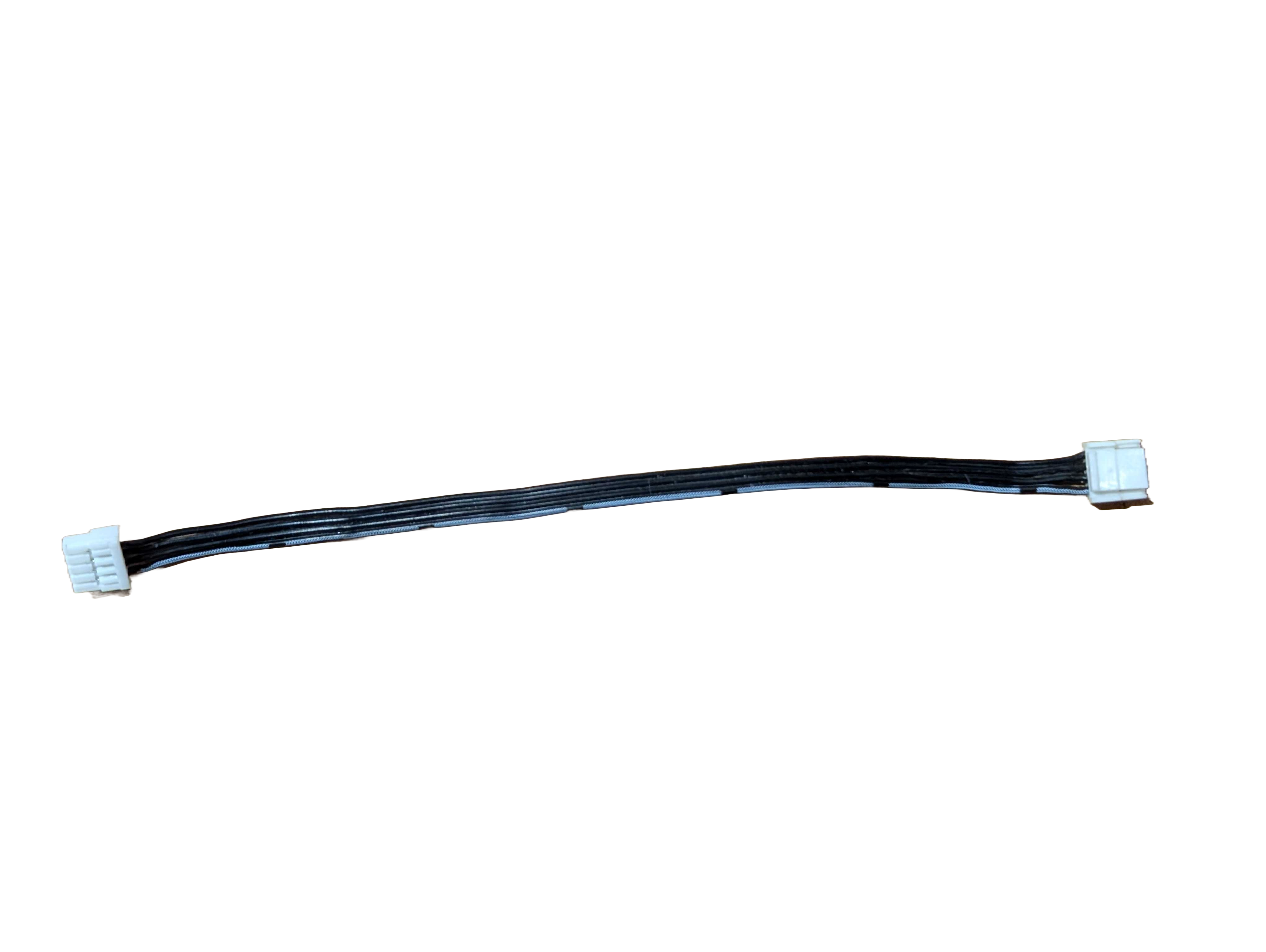
Rs485 Module Cable |
1. Overview of the A1 Motor
The A1 motor is a state-of-the-art, highly integrated permanent magnet synchronous motor (PMSM) designed specifically for robotics applications. Its compact design integrates several critical components that work together to deliver high performance and precise control.
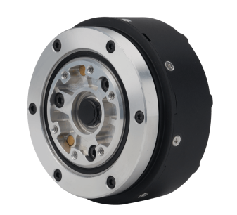
Key Components:
Stator and Rotor: The stator houses the motor’s windings, while the rotor is the moving part that generates motion.
Drive Plate: This part controls the motor’s operation by regulating power delivery.
Reducer: A gearbox that reduces the motor’s speed and increases torque output.
Encoder: A sensor that provides feedback on the motor’s position and speed, essential for precise control.
Bearing: Ensures smooth rotation of the motor’s moving parts.s
Key Parameters:
Operating Voltage: 24V-30V
Rated Voltage: 24V
Maximum Torque: 33.5Nm
Maximum Speed: 21 rad/s
Communication Protocol: RS-485
This motor is specifically engineered for high-performance applications, such as in robotic systems, where reliability, precision, and power efficiency are critical.
2. RS-485 Interface Connection
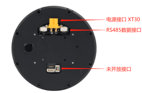
The RS-485 interface is a standard communication protocol used in industrial and robotic applications due to its robustness in noisy environments and ability to support long-distance communication.
Connecting the A1 Motor:
The A1 motor features two equivalent RS-485 interfaces, allowing for the daisy-chaining of multiple motors. This means you can control up to three motors in series using a single RS-485 line.
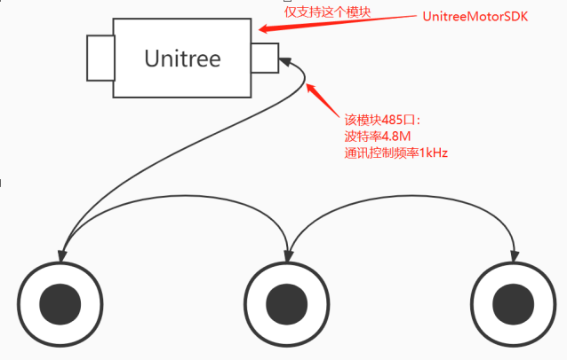
To control the motor from a computer, connect the RS-485 interface of the motor to your computer via a USB-to-RS-485 converter.
Power Supply: Ensure that a 24V DC power supply is connected to the motor. Once powered, the motor’s green indicator light will blink, signaling that it is ready for operation.
Note
The communication frequency for controlling the A1 motor is up to 3 kHz, which allows for fast and responsive motor control, essential in dynamic robotic applications.
3. Configuring Motor IDs
In a multi-motor setup, each motor must be uniquely identified on the RS-485 communication line. This is achieved by assigning each motor a unique ID.
Each motor connected via the RS-485 serial port must have a unique ID for individual control. The following instructions explain how to modify the motor ID using the SDK.
I. Clone and Build the SDK
First, clone the Unitree Actuator SDK (A1B1 branch) and build it.
Steps to Clone and Build:
Open a terminal window.
Clone the repository:
git clone -b A1B1 https://github.com/unitreerobotics/unitree_actuator_sdk.gitNavigate to the SDK directory:
cd unitree_actuator_sdkCreate a
builddirectory and compile the code:mkdir build cd build cmake .. make
After successful compilation, you should see an executable file named changeID in the build directory.
II. USB to RS-485 Connection
The A1 robot motors are controlled via an RS-485 serial port, which is accessed through a USB-to-RS-485 module. This module allows communication between the motors and your computer.
Steps to Check the Serial Port Name:
Connect the USB-to-RS-485 module to your computer.
On Linux, the system will assign a serial port name starting with
ttyUSB. To identify this port, run the following commands:cd /dev ls | grep ttyUSB
The command will display the connected serial port, e.g., /dev/ttyUSB0.
III. Changing Motor ID
Each motor needs a unique ID for control. You will modify the motor ID using the changeID program from the SDK.
Steps to Change Motor ID:
Navigate to the
builddirectory where thechangeIDexecutable is located:cd buildRun the
changeIDprogram with administrator privileges:sudo ./changeIDYou will be prompted to enter the administrator password. After entering the password, the program will start.
Enter the serial port name (e.g.,
/dev/ttyUSB0) when prompted. This will put all motors into “ID modification mode”. In this mode, the motor output shaft behaves like an electronic ratchet, meaning you will feel resistance when rotating it manually.Use the following steps to set the motor ID:
Rotate the motor output shaft using the provided tooling (M4 screws with a depth of no more than 5mm).
The motor ID will be set based on the number of turns:
One turn sets the ID to
0(Hip Motor).Two turns set the ID to
1(Thigh Motor).Three turns set the ID to
2(Calf Motor).
After setting the ID, type
ain the terminal and press Enter to save the motor ID.
Note
The “turns” referred to here are not full rotations but the distinct incremental steps (jerks) you will feel while rotating the motor shaft in ID modification mode. These jerks indicate the motor is in the electronic ratchet mode, and each jerk corresponds to a new ID being assigned.
Important
Ensure the tooling screws are M4 and inserted no deeper than 5mm into the motor shaft.
The IDs can only be
0,1, or2.
Following these steps will allow you to successfully modify the motor IDs for Unitree A1 Robot motors. For any further issues or troubleshooting, refer to the Unitree Actuator SDK documentation.
4. Testing Motor Configuration
After assigning and saving the motor IDs, it’s essential to verify that the motors are correctly configured and operational.
Verifying Motor Operation:
Modify and Compile Test Program: - The SDK includes a test program named
main.cpp. Before running this program, open the code and set the correct motor ID and serial port name. - Compile the program by navigating to the SDK directory and using the following commands:
mkdir build cd build cmake .. make sudo ./main
Running the Test: - Execute the compiled test program. This program will command the motor to perform basic operations such as rotating to specific positions. - The program will display important motor parameters on your screen, including position, temperature, and any error codes that might indicate issues with the motor or its configuration.
5. Troubleshooting
In the event of issues during the configuration process, the following are common problems and their solutions:
Common Issues and Solutions:
Incorrect Serial Port or Missing Adapter: Ensure that the correct serial port is selected, and the USB-to-RS-485 adapter is properly connected.
Insufficient Privileges: If you encounter permission issues, rerun the program with
sudoto ensure it has the necessary access.Incorrect Motor ID: Double-check that each motor has been assigned a unique ID and that the ID matches what you specified in the test program.
No Power Supply: Confirm that the 24V power supply is connected and the green indicator light on the motor is blinking.
Communication Failure: Check all connections between the motor, RS-485 module, and computer to ensure there are no loose or faulty wires.
Additional Resources: For more detailed troubleshooting, consult the SDK documentation or the motor’s manual. These resources provide in-depth information on advanced configurations and debugging.
This guide provides comprehensive steps for configuring motor IDs on the A1 robot. By following these instructions carefully, you can ensure your motors are correctly identified and ready for precise control in your robotic application. For any advanced configurations or troubleshooting beyond this guide, refer to the documentation provided with the A1 motor or seek support from the manufacturer.