About R1

Component Overview
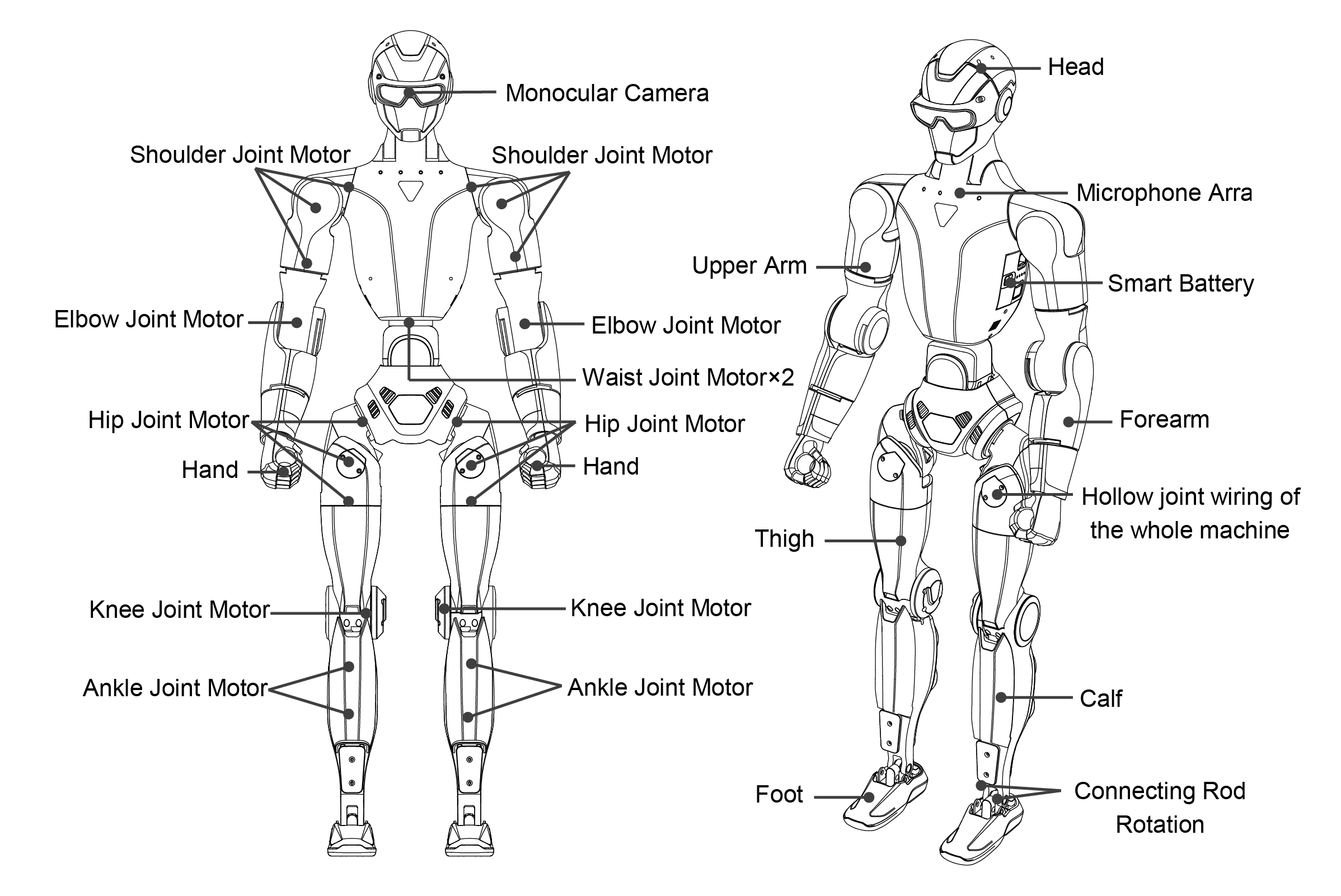
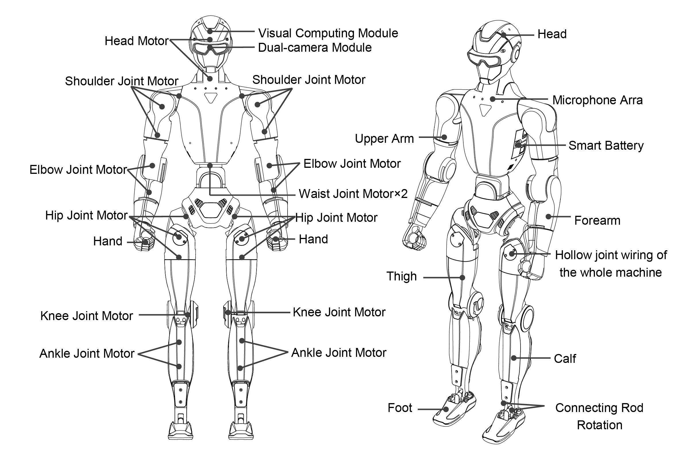
The Unitree R1 humanoid robot is composed of an upper body and a lower body, featuring a modular mechanical structure with multiple degrees of freedom (DOF) to support precise motion and posture control. Depending on the selected model, the R1 offers different joint configurations to balance weight, flexibility, and functionality.
Each leg is designed with six degrees of freedom, incorporating the hip, thigh, knee, and ankle joints to ensure stable locomotion and adaptable movement. The arms are available in two configurations, providing either four or five degrees of freedom, including the shoulder, upper arm, and elbow joints. The Air variant features a simplified arm design with a reduced elbow configuration.
The waist module is offered in two versions: a fixed configuration with no degrees of freedom, and an articulated configuration with two degrees of freedom, corresponding to the lumbar joint. Similarly, the head module is available in either a fixed (0-DOF) configuration or a 2-DOF articulated neck, enhancing environmental perception and sensor orientation. The Air variant does not include waist or head articulation.
Based on these configurations, the R1 series is divided into the R1 Air, R1 Basic, and R1 EDU models. These variants provide a total of 20 or 26 degrees of freedom, enabling accurate whole-body motion control and flexible posture adjustment across a wide range of applications.
Degrees of Freedom by Model
Category |
R1 Air |
R1 Basic / R1 EDU |
|---|---|---|
Total DOF |
20 |
26 |
Single Leg DOF |
6 |
6 |
Waist DOF |
0 |
2 |
Single Arm DOF |
4 |
5 |
Head DOF |
0 |
2 |
Component Description
R1 Air
R1 Basic / R1 EDU
Dexterous Hand (Dex3-1)
Overview
The Dex3-1 dexterous hand is a compact, force-capable end-effector designed for precise manipulation tasks in humanoid robot applications. Featuring a three-finger configuration and multiple sensing elements, the Dex3-1 enables fine-grained object interaction while maintaining a lightweight and robust design.
Electrical Parameters
Parameter |
Specification |
|---|---|
Operating Voltage |
12–58 V |
Sensing Range |
10 g – 2500 g |
Total Degrees of Freedom |
7 |
Array Sensors |
9 |
Degrees of Freedom Configuration
The Dex3-1 hand provides a total of seven active degrees of freedom, distributed as follows:
Thumb: 3 active degrees of freedom
Index Finger: 2 active degrees of freedom
Middle Finger: 2 active degrees of freedom
This configuration enables both power grasping and delicate manipulation, supporting a wide range of interaction scenarios.
Joint Motion Ranges
The allowable joint angle ranges for each finger are defined below:
Thumb: - 0° to +100° - −35° to +60° - −60° to +60°
Index and Middle Fingers: - 0° to +90° - 0° to +100°
These ranges provide sufficient flexibility for stable grasping, finger coordination, and controlled contact with objects.
Usage Guidelines
When operating the Dex3-1 dexterous hand, users should ensure that the robot’s motion planning prevents unintended contact between the hand and the robot body. If necessary, increasing the outward offset of selected shoulder joints can help reduce the risk of self-collision.
During development and testing, it is recommended to avoid highly dynamic or strenuous behaviors—such as running or balance stress tests—while the dexterous hand is active. This helps protect the mechanical structure and ensures reliable operation during manipulation-focused tasks.
Mounting Hole Positions
Front Chest Mounting Holes
The Unitree R1 provides mounting points on the front chest area for installing external components or accessories. If access to these mounting holes is required, follow the procedure below carefully.
Mounting Preparation Procedure
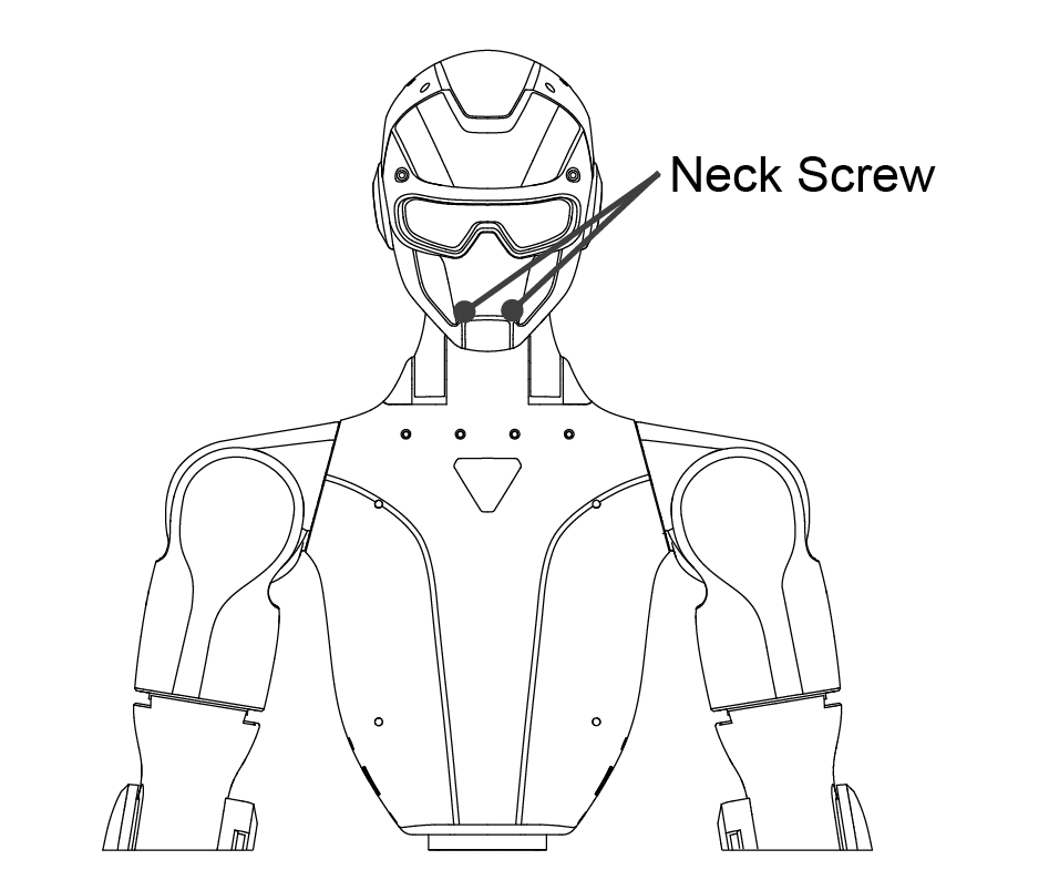
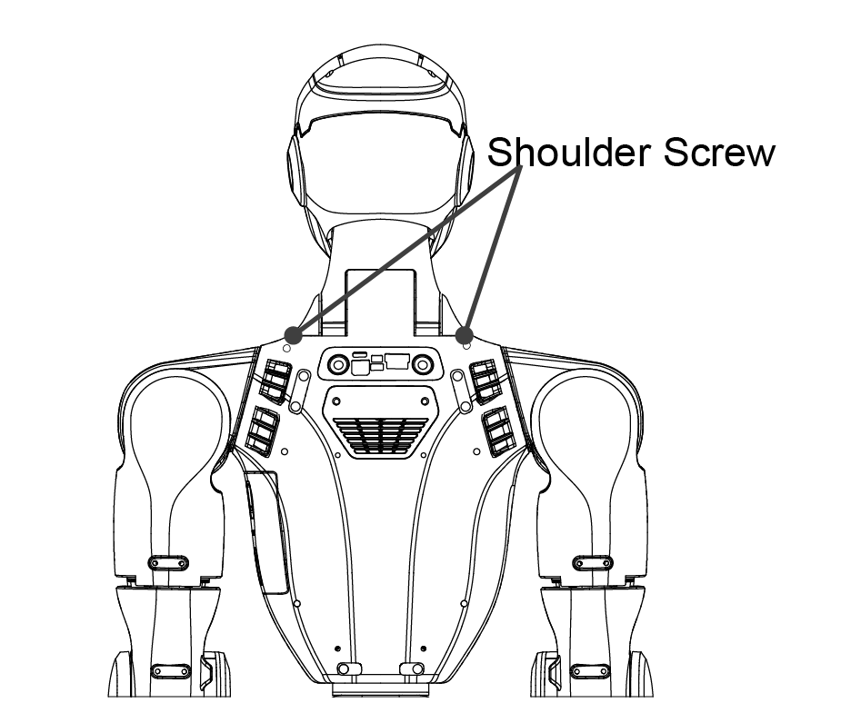
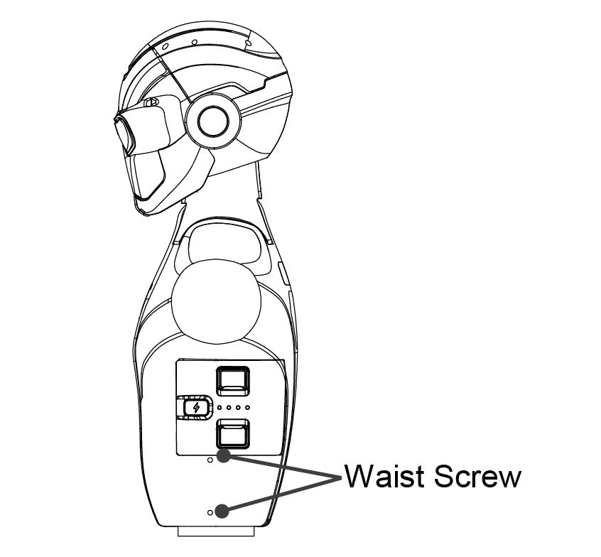
Remove fixing screws Detach the following screws as indicated in the reference diagram:
Two neck fixing screws from the front
Two shoulder fixing screws from the rear
Four waist fixing screws from both sides
Drill front panel holes From the inside of the front panel, use a 3.3 mm drill bit to carefully drill through the existing front panel screw holes.
Tap mounting threads From the inside of the front panel, use an M4 tap to create threads along the existing M4 threaded paths. Take care to align the tap correctly and avoid damaging the internal threads.
Front |
Back |
Side |
Mounting Hole Specifications
Thread Type: M4 threaded hole
Units: millimeters (mm)
Refer to the R1 Mounting Hole Dimension Diagram below for detailed hole positions and spacing before installation.
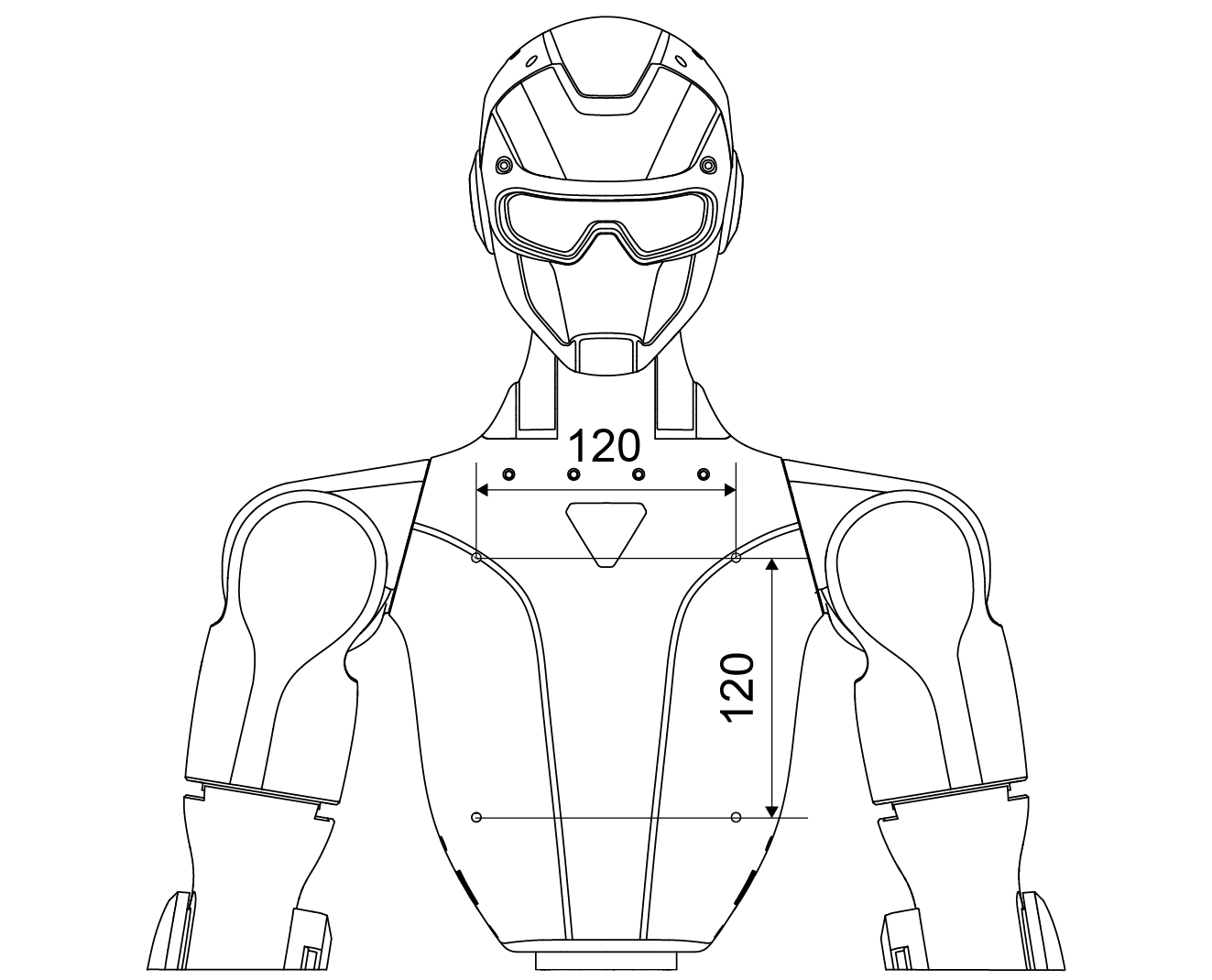
Front |
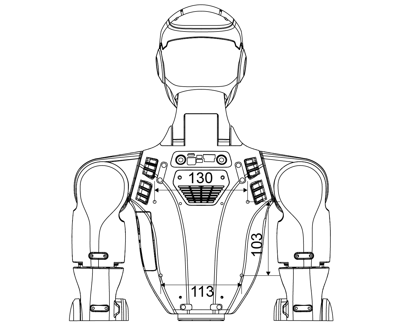
Back |
Important
Ensure all drilling and tapping operations are performed with the robot powered off and the battery removed. Improper handling may damage internal structures or compromise mechanical integrity.
Electrical Interfaces
The upper section of the Unitree R1 is equipped with multiple electrical interfaces used to connect joint motors, sensor peripherals, networking equipment, and external control devices. This interface layout is designed to support convenient system debugging, fault diagnosis, and secondary development activities.
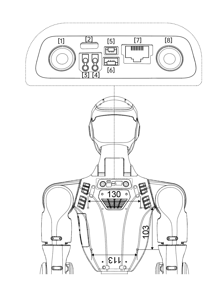
Interface List
No. |
Interface Type |
Abbreviation |
Description |
|---|---|---|---|
1 |
Reserved Button |
Reserved Button |
Not connected (NC) |
2 |
Type-C |
Type-C |
Supports USB 3.0 devices; used on EDU version to connect to the rear computing module |
3 |
XT30UPB-F |
24V |
24 V / 3 A power output |
4 |
XT30UPB-F |
36V |
36 V / 5 A power output |
5 |
GH1.25 |
Emergency Stop Interface |
External emergency stop interface |
6 |
GH1.25 |
Reserved Socket |
Not connected (NC) |
7 |
RJ45 |
1000 BASE-T |
Gigabit Ethernet interface |
8 |
Button |
STOP |
Integrated emergency stop button |
External Emergency Stop Interface
The external emergency stop interface uses a GH1.25 connector. Pin assignments are defined from left to right as shown below.
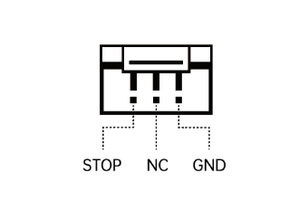
Pin Number |
Signal |
|---|---|
1 |
STOP |
2 |
NC |
3 |
GND |
Important
When connecting external power or emergency stop devices, ensure correct voltage levels and pin alignment. Improper connections may result in system malfunction or hardware damage.
Onboard Computer
Overview
The R1-EDU Professional Edition is equipped with a dedicated Development Computing Unit, designed specifically to support secondary development, algorithm deployment, and advanced perception or control workloads. This onboard computer provides sufficient computing performance for real-time processing, AI inference, and system integration tasks.
Development Computing Unit Specifications
Parameter |
Specification |
|---|---|
Model |
NVIDIA Jetson Orin NX |
CPU Architecture |
Arm® Cortex®-A78AE |
CPU Core Count |
8 |
Thread Count |
8 |
Max Turbo Frequency |
Up to 2.0 GHz |
GPU |
1024-core NVIDIA Ampere GPU with 32 Tensor Cores |
Max GPU Frequency (Dynamic) |
918 MHz |
Video Memory |
16 GB |
System RAM |
16 GB |
Cache |
2 MB L2 + 4 MB L3 |
Storage |
2 TB |
Instruction Set |
64-bit |
OpenGL Support |
Version 4.6 |
OpenCL Support |
Version 3.0 |
DirectX Support |
Version 12.1 |
Network Configuration
Default IP Address:
192.168.123.164
This address is preconfigured for communication and development access within the robot’s internal network.
Usage Notes
The Development Computing Unit is intended exclusively for secondary development purposes.
Default login credentials are provided for initial access:
Username:
unitreePassword:
123
The computing module shipped with the robot may be replaced with a newer or higher-performance version, provided that its performance is not lower than the specifications listed above.
Important
For security reasons, users are strongly advised to change the default login credentials after first access. Ensure proper shutdown procedures are followed before performing any hardware or software modifications.
Camera Field of View (FOV)
The Unitree R1 is equipped with wide-angle vision systems designed to provide strong visual perception and spatial awareness. Depending on the model variant, the robot uses either a monocular or binocular camera configuration to support perception, navigation, and interaction tasks across diverse environments.
Camera Configurations by Model
R1 AIR
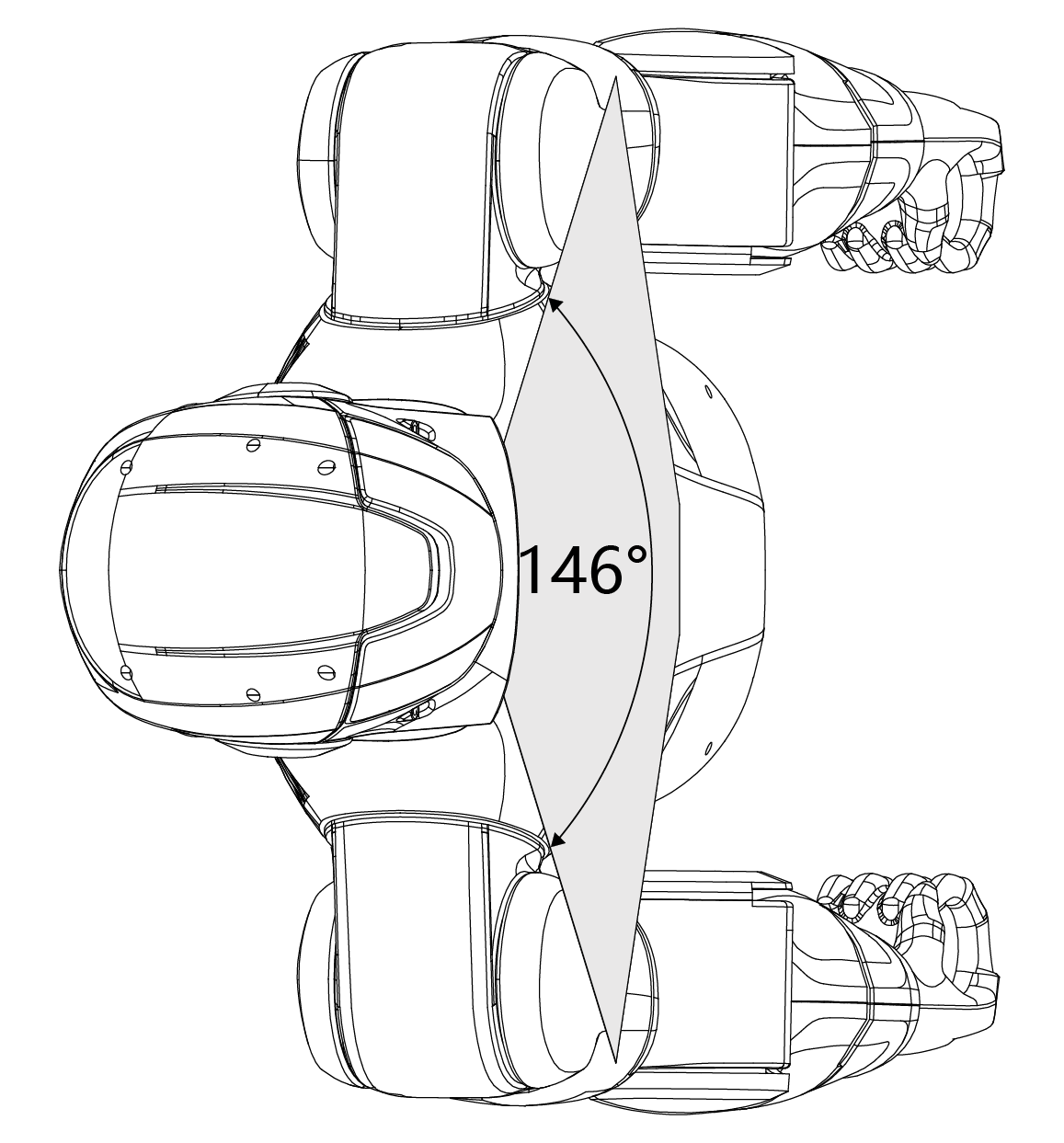
The R1 AIR head integrates a monocular camera with a horizontal field of view of up to 146° and a maximum vertical field of view of 110°. This configuration provides broad visual coverage while maintaining a lightweight design.
R1 Basic / R1-EDU
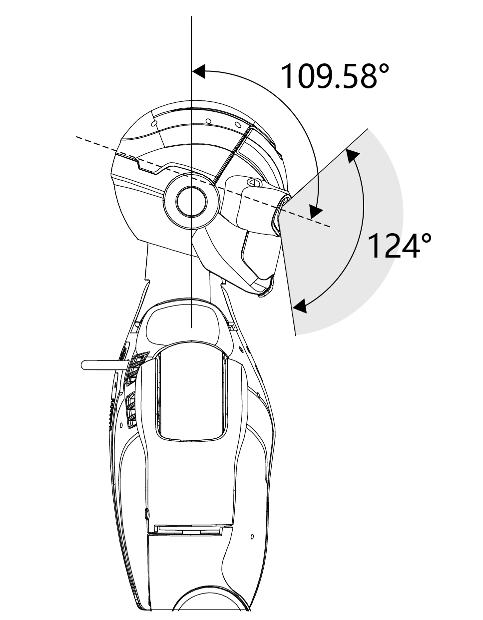
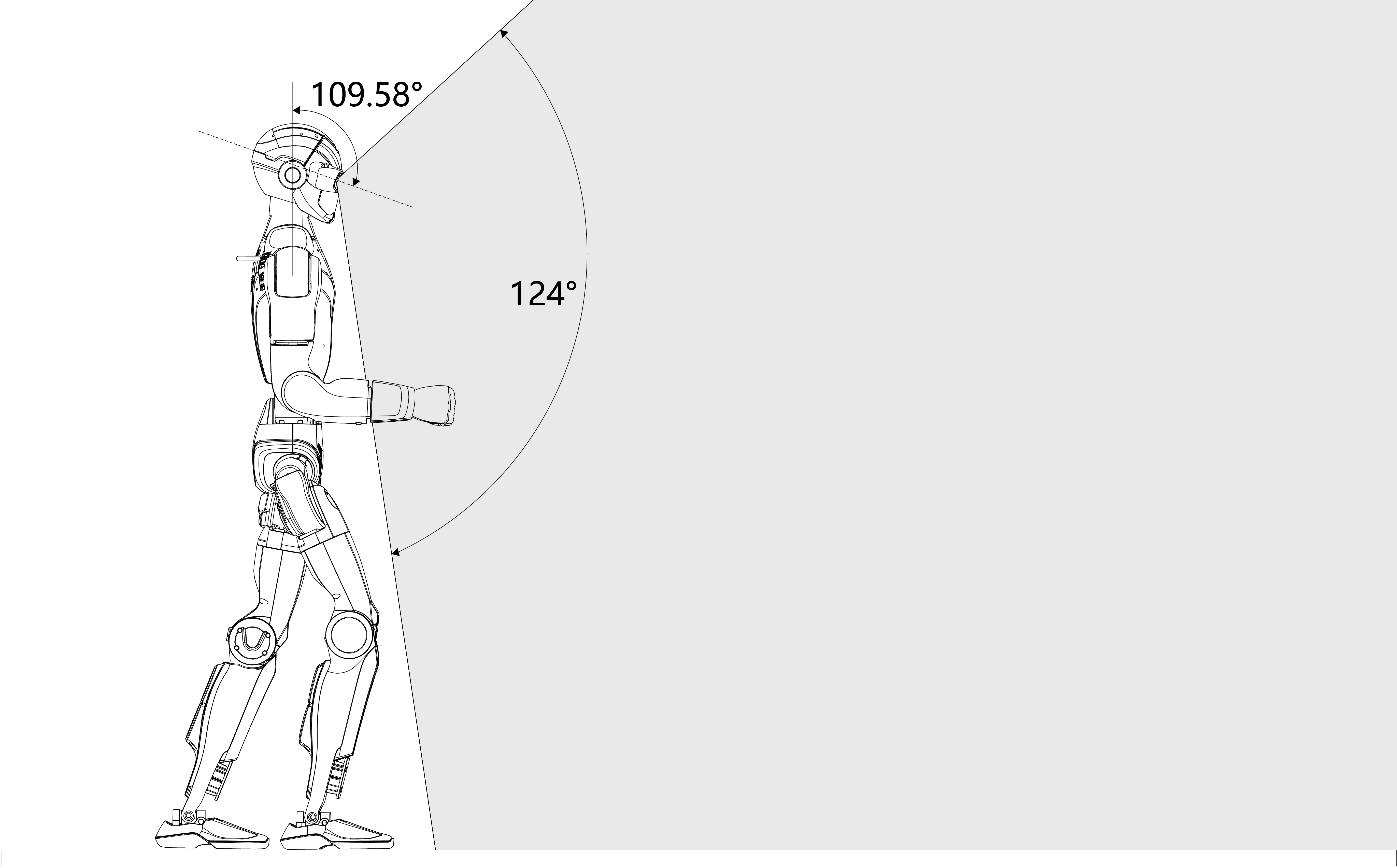
The R1 Basic and R1-EDU models are equipped with a binocular depth camera module, offering a horizontal field of view of up to 150° and a maximum vertical field of view of 124°. This setup enables depth perception and enhanced spatial understanding.
Vertical Field of View Example
When using the binocular camera module, the effective vertical field of view is influenced by the head’s pitch motion range. For example, a vertical FOV of approximately 109.58° corresponds to the available head pitch movement range, allowing the robot to actively scan its surroundings.
Horizontal FOV |
Vertical FOV |
Perception Capabilities
The R1’s wide field of view significantly enhances visual perception, enabling accurate environmental understanding, reliable obstacle detection, and high-precision spatial awareness. These capabilities allow the robot to respond intelligently and adapt flexibly to a wide range of real-world scenarios, including navigation, interaction, and perception-driven tasks.
Single Camera Technical Parameters
Category |
Specification |
|---|---|
RGB Full Resolution |
1280 × 1088 |
Depth Resolution |
544 × 448 |
Depth Frame Rate |
10 Hz |
RGB Frame Rate |
30 Hz |
Sensor Resolution |
13 Megapixels |
Shutter Type |
Global shutter |
Dynamic Range |
66 dB (Normal mode) / >100 dB (HDR mode) |
Infrared Enhancement |
850 nm / 940 nm near-infrared support |
Gain Control |
15.5× analog gain, 16× digital gain |
Exposure Control |
Auto exposure and gain control; supports exposure < 1 line |
Advanced Features |
HDR output, high photosensitivity, high SNR, LED strobe, external exposure control, multi-sensor synchronization, horizontal/vertical window adjustment, interface register programming |
Note
Actual field of view and perception performance may vary depending on configuration, lighting conditions, and operational posture of the robot.
Joint Motors
The Unitree R1 is equipped with self-developed joint motors engineered for high performance, compact integration, and precise motion control. Each motor features a hollow-shaft design, reducing overall weight while enabling efficient internal routing of cables and mechanical components.
To support accurate control and state estimation, the joint motors are fitted with dual encoders, providing high-resolution feedback for both position and velocity. This design meets the requirements of high-precision control, dynamic motion execution, and stable whole-body coordination.

|

|

|
Joint Indexing and Motion Limits
The table below lists the joint sequence numbers, joint names, and corresponding motion limits (in radians). Entries marked as EMPTY indicate reserved or unused joint indices.
Joint No. |
Joint Name |
Limit (rad) |
|---|---|---|
0 |
L_LEG_HIP_PITCH |
−2.9322 ~ 2.5482 |
1 |
L_LEG_HIP_ROLL |
−1.0472 ~ 1.7453 |
2 |
L_LEG_HIP_YAW |
−2.7402 ~ 2.7402 |
3 |
L_LEG_KNEE |
−0.1745 ~ 2.4260 |
4 |
L_LEG_ANKLE_PITCH |
−0.8727 ~ 0.5760 |
5 |
L_LEG_ANKLE_ROLL |
−0.2618 ~ 0.2618 |
6 |
R_LEG_HIP_PITCH |
−2.9322 ~ 2.5482 |
7 |
R_LEG_HIP_ROLL |
−1.0472 ~ 1.7453 |
8 |
R_LEG_HIP_YAW |
−2.7402 ~ 2.7402 |
9 |
R_LEG_KNEE |
−0.1745 ~ 2.4260 |
10 |
R_LEG_ANKLE_PITCH |
−0.8727 ~ 0.5760 |
11 |
R_LEG_ANKLE_ROLL |
−0.2618 ~ 0.2618 |
12 |
WAIST_YAW |
−2.6180 ~ 2.6180 |
13 |
WAIST_ROLL |
−0.5236 ~ 0.5236 |
14 |
EMPTY |
EMPTY |
15 |
L_SHOULDER_PITCH |
−3.1416 ~ 2.0944 |
16 |
L_SHOULDER_ROLL |
−2.4784 ~ 0.2269 |
17 |
L_SHOULDER_YAW |
−1.9199 ~ 1.9199 |
18 |
L_ELBOW |
−0.9757 ~ 2.1850 |
19 |
L_WRIST_ROLL |
−1.9199 ~ 1.9199 |
20 |
EMPTY |
EMPTY |
21 |
EMPTY |
EMPTY |
22 |
R_SHOULDER_PITCH |
−3.1416 ~ 2.0944 |
23 |
R_SHOULDER_ROLL |
−2.4784 ~ 0.2269 |
24 |
R_SHOULDER_YAW |
−1.9199 ~ 1.9199 |
25 |
R_ELBOW |
−0.9757 ~ 2.1850 |
26 |
R_WRIST_ROLL |
−1.9199 ~ 1.9199 |
27 |
EMPTY |
EMPTY |
28 |
EMPTY |
EMPTY |
29 |
HEAD_PITCH |
−0.6283 ~ 0.6283 |
30 |
HEAD_YAW |
−1.8326 ~ 1.8326 |
Note
Joint limits are defined in radians and may vary depending on hardware configuration, firmware version, and operational conditions. Always ensure commanded joint motions remain within the specified limits.